|
|
|
|
| |
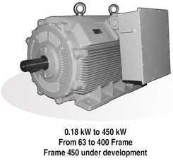
TEFC Motors |
| |
 |
|
ENERGY EFFICIENT MOTORS LEVEL 2 |
|
| |
|
| |
Energy Efficiency level
2 as per IS:12615 |
| |
Energy Efficiency as
per CEMEP Standards prevalent in Europe |
| |
'V' seal arrangement up
to 355 frame - Easier assembly of bearing housing |
| |
Integral bearing cover
with endshield up to 225 frame |
| |
Larger terminal box for
accommodating bigger Aluminium cables |
| |
Sophisticated CNC
Machines, Most
Advanced Manufacturing Technology &
Test Plant - Improved reliability. |
|
| |
STANDARD
SPECIFICATIONS
| |
|
| RANGE |
0.18 kW
to 400 kW (FRAME 63 to 400)
Multi speed options are also available |
| VOLTAGE |
415 V +/- 10 % |
| FREQUENCY |
50 Hz +/- 5 % |
| COMBINED VARIATION |
+/- 10 % (ABSOLUTE
SUM) |
| INSULATION |
Class 'F' (Temp. rise
limited to class 'B' ) as standard |
| AMBIENT /
TEMPERATURE RISE |
50 0C / 70
0C |
| DEGREE OF PROTECTION |
IP55 AS PER IS: 4691 |
| |
|
|
| |
SPECIAL
DESIGNS OFFERED
|
ELECTRICAL |
MECHANICAL |
| Non
Standard Voltage And Frequency Variation |
Non
Standard Mounting Dimensions |
Duel
Voltage
Triple Voltage |
 |
Special shaft
Extension |
Inverter
fed Supplies And AC Variable Speed
drives |
Double shaft
Extension |
| Energy
Efficient Motors |
Low Vibration & Noise
Level |
| High Slip
Motors |
Shock Grade Motors |
Motors
For Frequent starts/stops/reversals
(e.g. crane duty) |
Motors for Hazardous
areas |
| Torque
Motors |
Motors For Dust Laden
Atmosphere |
| High
Frequency Motors |
Brake Motors |
| Textiles
Motors |
Canopy for horizontal
mounting motors |
|
10,12,16,18,24,32 Pole Motors |
Special Bearings like
Thrust Bearings |
| Special
Performance Requirements |
Tacho Mounting |
| Class H
insulated Motors |
Non Standard Paint
Shade and Painting Procedure for
required Dry Film Thickness |
| Motors
With Service Factor |
Fabricated Steel
Enclosure
Alternate Terminal Box Position |
Slipring
Motors with Bar-wound rotors for
Frames 280 to 400 |
Special Shaft
Material |
Motors
for operation on Variable Frequency
Drive - Refer note on next Pages |
Stainless Steel/
Brass Hardware
Accessories like Resistance Temperature
Detectors,
Bearing Temperature Detectors, Thermocouples,
Plug
& Socket |
| |
Custom Size
Fabricated terminal box & Terminal
Arrangements. |
 |
 |
|
| |
Top |
|
|
| |
Energy
Efficient Motors |
| |
 |
|
ENERGY EFFICIENT MOTORS LEVEL 1 |
|
| |
Crompton Greaves has
now developed a complete family of high efficiency
motors confirming to Eff level 1 standards of IEEMA
: 19-2000 and other applicable standards in Europe
and rest of the world.
These motors are available in TEFC
construction for use in safe areas and also in
flameproof enclosure for use in Hazardous areas. |
| |
|
|
SPECIAL DESIGN FEATURES : |
| |
Higher efficiencies are
achieved by following special features :
• Low loss special grade of thinner laminations.
This reduces the Iron loss even at partial loads.
• Thicker conductors and more copper contents
reduce copper loss due to lower resistance.
• Longer core length, reduced and uniform air gap
between stator and rotor to reduce stray losses .
• Special design of fan and fan cover to reduce
windage losses. |
| |
|
|
BENEFITS : |
Improved efficiency is available from 60 % to
100 % load. The eff curve is almost flat
resulting in higher energy savings as in most of
the cases the motor is not always fully loaded .
The special design features also result in lower
operating temperatures which enhance the life of
motor and reduce the maintenance costs.
These motors have inherently low noise and
vibration and help in conservation of
environment . Crompton Greaves energy efficient
motors offer an additional feature which no
other manufacturer offers.
These motors are with highest power factor in
the industry due the special exclusive designs
available with Crompton Greaves.
The higher power factor reduces the currents in
the cables supplying power to motor and this
reduces cable loss, improving the system
efficiency sometimes by even 2 %.
Sometimes this allows even a lower cable size
saving tremendously on capital costs. Saving is
also made by reducing capacitors required to
improve power factor. |
| |
|
MANUFACTURING RANGE : |
Efficiency Level 1
• 0.37 kW to 160 kW
• Frame sizes : 71 to 315 for TEFC 80 to 315 for
Flame proof
• The entire range is available in IEC frames
sizes (metric range) and also in NEMA frames |
|
| |
CONFORM TO
FOLLOWING STANDARDS :
• IEEMA : 19-2000
• IS 12615
• IS 325-1996 & IEC 60034
• NEMA EPACT EFFICIENCY VALUES (for NEMA motors)
IEEMA 19-2000 standard covers kW ratings only up to
160kW. However we are offering energy efficient motors
up to 450 kW. |
| |
IMPORTANCE OF
ENERGY EFFICIENCY :
|
Growing cost of energy calls for power saving at
each possible step of manufacturing. Electric
motor driven systems used in industrial
processes consume more than 70 percent of
electricity used in industry, hence best
possible technology is being applied for
achieving highest possible efficiency values. |
|
| |
EFFICIENCY MEASUREMENT OF AN ELECTRIC MOTOR
The efficiency of an electric motor is
determined by the amount of useful power it
produces compared to the amount of energy
required to operate it. The figure below
illustrates how a Crompton Greaves Energy
efficient motor effectively turns 1000 units of
electrical power into mechanical power.

Since motor efficiency is commonly expressed as
a percentage. Efficiency in this case would be
94%. |
|
| |
 |
|
ENERGY EFFICIENT MOTORS LEVEL 1 |
|
|
The benefits of using these motors are maximum in
continuous duty applications like Blowers,
Compressors, Fans, Exhausters Pumps etc. |
| |
|
|
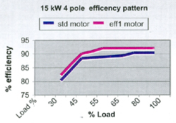
BEST PERFORMANCE EVEN AT PARTIAL LOADS : |
|
|
In many applications the load factor of the motor
will range between 60% to 80%. The efficiency curve
of standard motor is drooping in nature i.e there is
a sharp fall in efficiency at partial loads. But the
energy efficient motors have a flat efficiency curve
and hence the fall in efficiency is marginal. Thus
energy saving is significant even in part loads. |
| |
|
|
| |
|
| |
INTERNATIONAL APPROVALS CERTIFICATES
 |
| |
ASSESSING COST EFFECTIVENESS OF ENERGY EFFICIENT MOTORS
:
Savings :
Savings are calculated as follows :-
kW - out put of motor in kW
E1 - efficiency of standard motor
E2 - efficiency of energy efficient motor

|
Savings=X * |
 |
|
|
| |
EXAMPLE
3.7 kW
4 pole motor in frame ND112M
Std motor eff 2: 85 % eff1 88.3 %
Price eff2 : Rs 7215/- eff1: Rs 9380/-
Working hours 16 per day, working days 300 in a
year,
power rate Rs 4.50 per kWH
X = 0.1626
RS Savings = 0.1626X16X300X4.5
= 3514 /- RS per year
Extra investment RS 2615/-
Payback period = 9 months

Energy cost for a 15 years usage at Rs 4.50 /
kWH is staggering 14.10
lacs as compared to buying cost of Rs 7215/-.
Also the energy kWH rate
is likely to only go up in future.
If we compare initial purchase price of the
motor with the cost of energy
it uses over it working lifetime, the initial
cost represents less than two
percent of its lifetime cost in most of the
cases . |

So it makes a great deal of
sense to choose an eff1 level motor whenever
a motor is needed to drive any applications.
Combining this with usual Crompton greaves
motors reliability, wide service network
(over 180 service points all over India),
the wise choice is Crompton greaves EFF1
motor. |
|
| |
Top |
|
|
| |
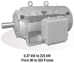
Flame Proof
Motors |
| |
 |
|
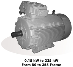
THE WIDEST AVAILABLE RANGE |
|
| |
SQUIRREL
CAGE MOTORS
0.37 kw to 355 kw (Frames E80 toE355 LX)
SLIP RING MOTORS
22 kw to 160 kw
(Frames EW 250 M to EW 315 L) |
| |
|
|
STANDARD SPECIFICATIONS |
| |
VOLTAGE :
415 ± 10% Other Voltage class
(220 V - 660 V) available on request. |
FREQUENCY :
50 ± 5% 25 HZ to 60 HZ available on request. |
Combined variation :
± 10 % (absolute sum) |
INSULATION :
Class F Class 'H' can be given on request. |
RATING/DUTY :
Continuous (S1) Intermittent duties
available on request. |
MOUNTING :
Horizontal foot mounting (B3)
Other mountings available on request. |
PAINT :
Epoxy anticorrosive painted surface
(Standard shade 631 as per IS - 5) |
AMBIENT / TEMPERATURE RISE :
450C/750C. Higher Amb.
upto 600C on request. |
TEMPERATURE CLASS :
T4 |
DEGREE OF PROTECTION :
IP 54 - E80 - E132 M
E225 M to E355 LX
(IP55 with canopy can be offered.)
IP55 - Frame E 160L to E 200 L. |
|
ERTL / CCOE (PESO) / DGMS approvals as a
standard feature. For BASEEFA approval
please contact nearest branch office/works. |
|
|
| |
|
|
| |
APPLICABLE
STANDARDS :
|
Enclosure |
IS 2148 EN 50018 |
| Performance |
IS325 BS 5000 (Part
10) IEC60034 -1 |
| Performance for
Mines |
IS 3682 |
| Dimensions Foot |
IS 1231 IEC60072-1 |
| Flange |
IS2223 BS4999 Part 414 |
|
| |
INDUSTRIAL
APPLICATIONS :
|
• Coal Mines. |
• Petro Chemicals & Chemicals. |
|
• Oil Mines & Rigs. |
• Fertilizers. |
|
• Solvent extraction plants. |
• Paints & Varnish Industry. |
|
• LPG Bottling plants. |
• Agro Chemicals. |
|
• Drugs & Pharmaceuticals. |
• General Industry. |
|
| |
SPECIAL
PURPOSE MOTORS FOR
|
1. Longwall mining equipment. |
|
2. High pressure mine ventilation fans with plug
& socket arrangement. |
| 3.
Auxiliary mine ventilation fans with rod
mounting / flange mounting. |
|
4. Belt
conveyors and armoured face/ chain conveyors. |
| 5. Side
dump loaders, load haul dumpers |
|
6.
Haulages (squirel cage and slipring motors). |
| 7.
Dewatering pumps. |
|
8.
Sucker rod pumps. |
| 9. Mud
agitators & mud pumps. |
|
10.
Slurry extraction pumps. |
| 11. Air
compressors & blowers. |
|
|
|
| |
SPECIAL
DESIGN FEATURES AVAILABLE
|
1. Dual voltage (550/1100V) with 9 terminal
connections as per NCB 625 |
|
2. Non standard voltage and frequency variation |
3. Dual voltage (1:2 or 1: ratio) Tripple voltage (1:
 : 2 ratio)
 |
|
4.
Energy efficient motors High slip motors Motors
for frequent starts/stops/reversals |
| 5.
10,12,16,18,24,32 pole motors |
|
6.
Special performance requirements |
| 7.
Class H insulated motors |
|
8. Low
vibration and noise level |
| 9.
Special Bearings |
|
10.
Tacho mounting |
| 11.
Special shaft material |
|
12.
Canopy |
13.
Plug & socket arrangement (30 to 300 Amps, 650 &
1100V) for
underground equipments. |
|
15.
Special RV/RA for slipring motors. |
| 16.
Space heaters, thermisters. |
|
17.
Multispeed motors. |
| 18.
Double /taper/non standard shaft extention |
|
19. Non
standard paint shade |
| 20.
Motors for use with variable frequency inverter
supply |
|
|
|
| |
TERMINAL
BOX AND TERMINAL ARRANGEMENT
|
• Cast iron construction, forming a separate
flame proof enclosure capable of containing
internal explosions |
|
• Standard position on right hand side viewed
from driving end side except in frames E 80,
E/EW 315 L & E 355 LX where it is on top. |
|
• Terminal box on top on specific request. |
|
• New
terminal box with spigotted cover & gland
plate/sealing box in frames E 160 to 355 LX with
following advantages |
|
• Inherently IP 55. |
|
• Spaciously designed for accommodating bigger
cables. |
|
• Double decker terminal arrangement for easy
termination of two cables. |
|
• Anti
loosening terminal arrangement |
| • For
slipring motors, separate terminal box for
stator & rotor terminations provided. Stator
terminal box is on left hand side while rotor
terminal box is on right hand side, viewed from
driving end. |
|
• Conduit plate is provided as standard while
sealing box provided for
group I gases. |
|
• Separate terminal box for auxiliary terminals
(space heaters, thermisters) for frame 225 and
above on request. |
|
|
|
| |
TERMINAL STUD
|
• Fully non hygroscopic thermosetting moulded
glass filled compound. |
|
• Increased clearances & creepages. |
|
• Anti loosening arrangement. |
|
• Metallic bush insert to take tightening
pressure. Eliminates breakage of insulation
(E160-315LX frames) |
|
| |
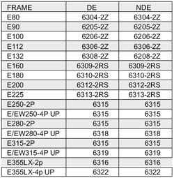
BEARING CHART :
|
| |
|
BEARING CHART : |
|
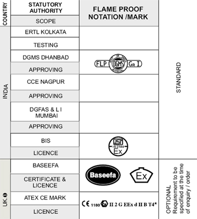
STATUTORY APPROVALS : |
 |
|
 |
|
| |
FLAMEPROOF MOTORS FOR GROUP IIC ATMOSPHERE
A complete range of Crompton
Greaves flameproof squirrel cage motors for gas group
IIC is now available for Indian Industries as an import
substitute. The motors are manufactured as per the most
stringent requirements for IIC atmosphere. The motors
are duly tested at ERTL. For more details, please
contact our nearest branch office / works.

AVAILABLE Pending for approval.
* STANDARD Temperature class T4. Other classes
available on request. * For IIA, IIB Gas Groups |
| |
|
CMRI |
: |
CENTRAL MINING RESEARCH INSTITUTE, DHANBAD. |
| DGMS |
: |
DIRECTORATE GENERAL OF
MINES SAFETY, DHANBAD. |
| CCE |
: |
CHIEF CONTROLLER OF
EXPLOSIVES, NAGPUR. |
| DGFAS & LI |
: |
DIRECTORATE GENERAL
FACTORY ADVICE SERVICE & LABOUR INSTITUTE, MUMBAI. |
| BIS |
: |
BUREAU OF INDIAN
STANDARDS, NEW DELHI. |
| BASEEFA |
: |
BRITISH APPROVALS
SERVICE FOR ELECTRICAL EQUIPMENT IN FLAMMABLE
ATMOSPHERES, UK. |
| ATEX |
: |
EUROPEAN DIRECTIVE |
| ERTL |
: |
ELECTRONIC REGIONAL
TEST LABORATORY |
NOTE:* Motors as per UK based standards can
be supplied against specific enquiries. |
| |
Top |
|
|
| |
Crane Duty Motors |
| |
|
APPLICATION : |
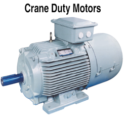 |
Prabal series squirrel cage/slip ring Crane duty
motors are specially designed for service on
cranes and hoists. They can also be used for
similar applications such as material handling
equipments, and cranes of all types. These
motors can serve as auxiliary motors in rolling
mills or wherever intermittent duty drives are
required.
These are duty type rated
motors developing high starting torque with
low starting current. The motors are
suitable for frequent starts/ stops and
reversals. Also rapid acceleration is
achieved by high pull out torquelrotor
inertia ratio. |
|
| |
TYPICAL APPLICATIONS :
Crane duty motors are
used for following applications in majority: Cranes
& hoists: long travel drive, cross travel drive,
main hoist, auxiliary hoist. Material handling
equipments: various conveyors Lifts Rolling mills |
| |
RANGE :
Manufacturing range for
cast iron slip ring crane duty motors is from 112 to
400 frame. The same for squirrel cage motors in cast
iron enclosure is from 80-400 & in aluminium
enclosure is from 63-160.
|
| |
MOUNTING :
Squirrel cage crane duty
motors are supplied with horizontal foot- mounting.
However, motors suitable for foot / flange / face
mounting or any combination of these with vertical
or horizontal orientation can be offered when
required. Slip ring motors are normally available
with foot mounting Flange mounting can be supplied
on specific request. |
| |
POWER
SUPPLY :
Crane duty motors are
suitable for 3 phase supply and can be wound for
any single voltage from 220 to 650 volts and
frequencies from 50 Hz or 60 Hz. The rotor
voltage is committed for stator supply of 415 V,
50 HZ.For other supply conditions, Rv to be
confirmed from CG. |
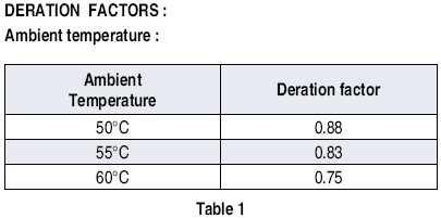
AMBIENT TEMPERATURE :
The motors are rated at 45°C ambient
temperature. For temperatures, other than 45°C,
a deration factor has to be applied as indicated
below. |
|
| |
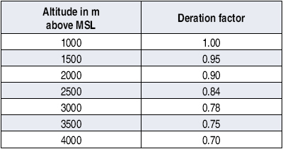
Altitude :
The motors are suitable for altitude upto 1000 m
above mean sea level. For altitudes more than this,
deration factor shall be as per below
STANDARD OPERATING CONDITIONS
|
Power supply |
: |
415 volts, 3 phase, 50 Hz |
| Voltage
variation |
: |
± 10% |
| Frequency
variation |
: |
± 10%
(absolute sum) |
| Ambient
temperature |
: |
45°C |
| Altitude |
: |
upto 1000m. |
|
| |
STANDARD SPECIFICATIONS
PERFORMANCE AND FIXING DIMENSIONS
The motors are manufactured with standard metric
frame sizes,
and they comply with the following standards (latest
versions).
IS: 325 IS:4722
IS:1231 IS:2223
IS:3177 IEC:60034-1
IS: 807
Motors with following steel plant specifications
also can be
supplied on request:
IPSS: 1-03-003 IPSS:1-03-004
For detail dimensions, please refer drawings on page
31-37 in this
publication. |
| |
CONSTRUCTIONAL FEATURES: (MECHANICAL)
STATOR FRAME AND ENDSHIELDS
Made of high quality cast iron conforming to
IS:210, ribbed externally to ensure maximum heat
dissipation. All components are machined on CNC
machines ensuring concentricity and correct
alignment. The windings and working parts are
completely enclosed and air is forced over the
stator body by fan, mounted on
the shaft and protected by a cowl. The feet are
integrally cast with the body. This ensures
sturdiness and resistance to vibrations.
STATOR AND ROTOR
CORES
Both the stator and rotor cores consist of low
loss and high permeability steel stampings which are
assembled under pressure and rigidly secured by end
plates.
ENCLOSURE AND COOLING
Standard crane duty motors have IP55 degree of
protection as per IS:4691. IP 56 & 66 can be
provided on request. The cooling code of motor is IC
411 as per IS:6362.
SHAFTS AND BEARINGS
The shaft is of high grade steel and of
appropriate diameter to withstand the bending and
torsional stresses. All shafts are ultrasonically
tested for any minor flaw in the material. Shafts
are machined to extreme fine limits to ensure fit
and interchangeability of bearings. The motors are
provided with single shaft extension.
Special shafl extensions like:
change in diameter and length,
-
taper shaft, with threaded end, and with
hexagonal nut and lock washer.
-
double shaft extensions, (cylindrical &
taper) are available on request.
|
| |
Motors are provided with deep groove ball
bearings. They are mounted with extreme care in dust
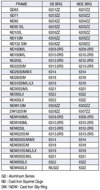
proof housing. (Refer bearing size table for
details). Sealed bearings are provided for motors
upto frame 225M. Grease lubricated bearings are used
on frames 250 and above. The correct amount of
grease is filled in the bearings during
manufacturing. On line greasing facility is provided
for 250 frame & above to facilitate greasing of
bearings without dismantling the motor.
For provision of insulated bearings, please refer to
CG.
PRABAL 'E' SERIES MOTORS
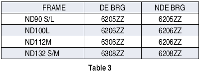
PRABAL SERIES MOTORS:
(Bearing references for single shaft extension)
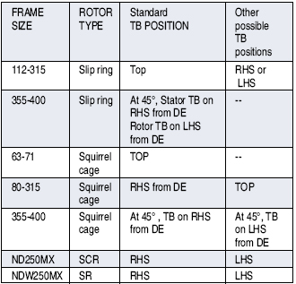
TERMINAL BOX
Terminal box is provided with IP55 degree of
protection. The box can be turned through 3600 in
steps of 900 to give cable entry from anyone of four
positions. The terminal boxes are suitable for BS
screwed conduit. However, fittings like double
compression type cable glands are available on
request.
Terminal box position can be provided as per table
below:
SLiPRING AND BRUSH GEAR
All sliprings are made of cupro-nickel. The slip
ring unit is having high insul~tion resistance
ensuring minimum wear and breakdown. The brush
holders are assembled as a complete unit which can
be easily replaced. The slipring enclosure is
dustproof & has a cover with accessibility for
inspection. The slip rings are epoxy moulded /
fabricated type as per requirement.
MOTOR GO. SQ.
For large no. of starts, it is necessary that the
accelerating time of the system should be as small
as possible. For this purpose, total inertia of the
system (motor GO sq. + Load GO sq.) should be
minimum. Motor GO sq. value and permissible load GO
sq. are indicated in the tables.
INTERCHANGEABILITY AND SPARES
All Prabal series crane duty motors are built to
standardised designs and all spare parts are
interchangeable.
CONSTRUCTIONAL FEATURES
(ELECTRICAL)
Class of Insulation:
Stator: Class F insulation with temperature rise
limited to class B
Rotor: Class H insulation with temperature rise
limited to class F
Prabal series crane duty motors with higher class
for stator insulation (class H) can also be offered
on request.
WINDINGS STATOR WINDINGS
Stator winding (and rotor winding in case of
slipring motors) consists of enamelled copper wire
impregnated with superior quality class F varnish
which is rigid at all working temperatures. Stators
in motors with frame 280 & above are manufactured
with vacuum pressure impregnation process as a
standard. All rotors irrespective of frame size are
processed with vacuum pressure impregnation. This
gives added electrical & mechanical strength to the
winding for high number of starts. The varnish has a
high insulation resistance and excellent resistance
to moisture, saline atmosphere, acidic/ alkaline
fumes, and also to oil and grease. The
insulation gives complete reliability under all
atmospheric conditions, including humid tropical
climates. Stator and rotor wound packs are subjected
to surge test before impregnation.
ROTOR WINDINGS
1. Wound rotor
Rotors of slip ring motors are wound and impregnated
similar to stator windings. In addition, rotor
windings are braced with resiglass banding. This
gives protection against centrifugal forces
experienced by overhang during overs peed and
frequent reversals. Gelcoat is provided on the
winding overhang for better
consolidation and protection from vibration. Strip
wound rotors are provided on frames 355 and above.
2. Cage rotor
Rotors are of pressure diecast aluminium upto 355
frame. They are designed for high starting torque,
suitable for high number of starts. Cooling fins
cast integrally with the rotor cage, improve the
cooling action within the motor. All rotors (cage
and wound) are dynamically balanced to comply with
the requirements of IS: 12075
TERMINAL ARRANGEMENT
The terminals are mounted on a moulded base and are
enclosed in a box having an inspection cover. In
case of slip ring motors, three terminals for stator
and three terminals for rotor are terminated in
terminal box with adequate creepage and clearance.
The rotor terminals are in the same box as those of
the stator.
Separate terminal box for rotor terminals is
provided for NDW355LX & NDW400LX frames. This
simplifies wiring and maintenance.
EARTHING
One earthing terminal is provided in the terminal
box and two terminals on mounting feet.
ACCESSORIES:
Crane duty motors can be provided with various
accessories as per table below:
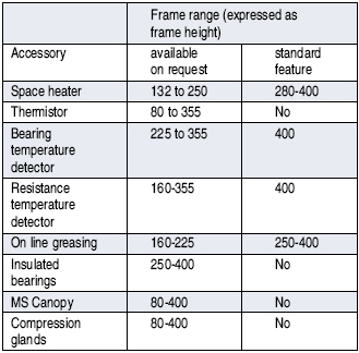
Space heating for anti
condensation:
Space heaters are used for avoiding accumulation of
moisture/water in humid atmospheres. In motors upto
200 frame size, motor windings can be heated up to
keep winding temperature above ambient by 5 to 10
degrees, by giving low supply voltage upto 10% of
rated voltage. Supply voltage is to be adjusted by
keeping 20-25% rated current. Thermal protection:
Stator windings can be provided with PTC thermisters
for alarm/trip or PT 100 type resistance temperature
detectors according to the accessories table
provided. Bearings can be provided with PT100 type
resistance temperature detectors as per enclosed
table 6.
ROTOR VOLTAGE
The rotor voltage of the motor is kept such that the
insulation of the rotor and of the associated
switchgear is not unduly stressed during rapid
plugging when rotor voltage can rise to 2 to 3 times
the rated value. Rotor voltage for slip ring motors
is as per performance tables enclosed. Special rotor
voltage can be offered for wire wound rotors with
confirmation from CG.
PULL OUT TORQUE
The pull out torque value at rated voltage is
indicated in the respective tables. Since available
torque varies as the square of the supply voltage at
motor terminals, an allowance for voltage drop in
long cables, live rails and collectors must be
considered. These voltage drops are significant when
motor is operated at pull out point, since current
at this point is much higher than the rated current.
Pull out torque is maximum for 300 starts/hour
class. This high pullout torque ensures rapid
acceleration irrespective of drop in effective
torque due to stepped rotor resistance. However,
care to be taken that gears and other drive
transmission equipments can withstand this peak
torque.
OVERLOAD CAPACITY
The motors can withstand 1.5 times the rated current
for 2 minutes without suffering damage. This feature
makes the motor suitable for severe duties
experienced on the crane or similar applications.
LIFE OF THE MOTOR
Crompton Greaves crane duty motors are designed and
manufactured with carefully selected and tested
insulating materials to ensure long services. The
life of the motor mostly depends upon the life of
the insulating materials since bearings, brush
gears, slip rings etc. can be replaced easily during
normal maintenance.
MAXIMUM PERMISSIBLE OPERATING SPEED
All 4, 6, 8, and 10 pole motors are designed for
withstanding an over speed of 2.5 times rated
synchronous speed or 2000 rpm whichever is less.
VFD CRANE DUTY MOTORS ( Cast Iron)
Crane duty squirrel cage motors when used with
inverter drives give better current control, speed
control & improved operation. Current control is
similar or better than slip ring motors &
maintenance cost /efforts are less than equivalent
slip ring motors. Current control of VFD driven
motors is better than standard squirrel cage motors.
Prabal series Inverter duty motors are provided with
special insulation system suitable to withstand
voltage spikes when fed from inverters. The motors
are provided with following features:
• Vacuum pressure impregnation of stator winding,
this gives less voids & stronger winding.
• Strengthened insulation system for withstanding
voltage stresses.
Standard features:
Base Voltage: 220 volts to 650 volts Base frequency:
50 or 60 Hz Insulation class: Class "F' or 'H' as
required (temp rise limited to class B)
CG make motors are suitable for the following IGBT
drive output
• High frequency in the range of 3kHZ - 6 kHZ.
Voltage rise time> 0.1 sec.
• Voltage spikes up to 1600V and rise time of 0.1
sec.
• Voltage spikes up to 1600V and rise time of 0.1
sec.
• THD < 3%
Mode of operation: Modes of operation of inverter
driven motors are classified according to type of
load & speed range. They are:
• Variable torque
• Constant torque
• Constant power.
|
| |
In case of cranes/hoists, the mode of operation is
constant torque. The typical speed range is from 10%
to 100% of synchronous speed. The speed during
lowering cranes in unloaded conditions may be more.
The limiting speed should not exceed 2.5 times of
rated synchronous speed or 2000 rpm whichever is
less.
The selection of frame size for various duty type &
starts shall be as per table enclosed.
For higher cable length from drive to motor, use
suitable dv/dt filters & a lower switching
frequency.
Use of insulated bearing at non driving is recommended
for frame size above 315 to reduce bearing failure
due to shaft currents.
Use of thermisters for frames upto 250 & resistance
temperature detectors for frame 280 & above is
recommended.
Additional losses & temperature rise:
Harmonics of voltage & current in a cage induction
motor supplied from a converter cause additional
iron & winding losses in the stator & the rotor.
There is no simple method to calculate the additional
losses & no general statement can be made about
their value.
When the motor is tested with converter supply at
rated load, base voltage & base frequency, the
permissible temperature rise will be within the
limits of the insulation system used. For example
when a motor havinf class F insulation system is
tested with sinusoidal supply at rated voltage ,
rated frequency & rated load, may have temperature
rise within class B limits. However, when the same
motor is tested with converter supply under same
test conditions, the temperature rise will be within
class F limits. It is assumed that, while testing
with converter supply, the HVF factor of converter
output supply, is maximum 3%.
Hence the outputs of crane duty inverter driven motors
are as listed in the table on page 28-30.
GENERAL REQUIREMENT:
All additional general requirements like accessories,
paint shade, insulation class, degree of protection,
voltage and frequency variation shall be available
at extra cost. The cost structure of extra features
is same as that for standard motors.
DEFINITIONS
The terms used frequently in intermittent duly drive
and hoisting are as bellow:
1. Duty:
Operation of the motor at load including no load and
de- energised period to which the motor is
subjected, including the sequence and duration.
2. Cyclic duration factor (CDF) :
The ratio between the period of loading including
starting and electric braking and the duration of
the duty- cycle expressed as percentage.
3. Starting:
The process of energizing a motor to bring it upto
rated speed from rest.
4. Jogging or inching:
This is an incomplete start during which the motor
does not attain more than 25% of the rated speed.
5. Electric braking:
A system in which a braking action is applied to an
electric motor by causing it to act as a generator.
6. D.C. Injection braking:
A form of braking of an induction motor in which a
separate dc supply is used to magnetise the motor.
7. Plug braking:
A form of electric braking of an induction motor
obtained by reversing the phase sequence of its any
two lines.
8. Regenerative braking:
A system of electric braking in which energy is
returned to the supply system.
INTERMITIENT DUTY TYPE RATINGS.
The basis of the ratings is that of
thermal capability, taking into account,
i) Frequency of starting
(starting class).
ii) Percentage of time during
each operating cycle the motor is energized, (CDF)
iii) The number and type of cycle per hour, (duty class)
iv) and the inertia of the motor and the load.
CLASSIFICATION OF STARTING:
The starting classification for a motor indicates the
maximum permissible number of starts per specified
inertia, taking into account complete starting,
jogging or inching and electric braking. Rating for
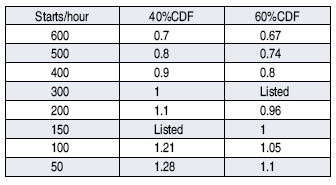
the commonly used starting, i.e. 6,150 and 300
starts/hour class, are listed in this publication.
However, following factors can be used to calculate
output rating for different number of starts and
CDFs.
Squirrel cage motors:
4 jogs or inchings or jerks = 1
start
1 plug braking = 3 starts
1 dc injection braking = 2 starts
1 plug reversal = 4 starts
Slip ring motors:
4 jogs or inchings or jerks = 1
start
1 plug bra~ng = 0.8 starts
1 plug reversal = 1.8 starts
DUTY TYPE :
Crane duty applications can be
classified into duty types S2 to S10. The duty types
are as per table 4 below:

The duty types S2 to S5 are
explained in detail as per below:
Short time duty (duty type S2) :
Operation at constant load during
a given time, less than that required to reach
thermal equilibrium, followed by a rest and de-
energised period of sufficient duration to
re-establish machine temperatures within 2°C of the
coolant. (See figure 1) The recommended values for
the short time duty are 10, 30 and 90 minutes.

Intermittent periodic duty (duty type S3) :
A sequence of identical duty cycle,
each including a period of operation at constant
load and a rest and de-energised period. These
periods being too short to attain thermal
equilibrium during one duty cycle. (See Fig. 2) In
this duty type, the starting current dose not
significantly affect the temperature rise. Unless
otherwise specified, the duration of the duty cycle
is 10 inutes. The recommended values for the CDF are
15, 25, 40 and 60 percent.

Intermittent periodic duty with starting (duty type
S4) :
A sequence of identical duty
cycles, each cycle including a significant period of
starting, a period of operation at constant load and
a rest and de-energised period. These periods being
too short to attain thermal equilibrium during one
duty cycle. (See Figure 3) In this duty, the
stopping of the motor is obtained either by natural
deceleration after disconnection of the supply or by
means of braking such as mechanical brake which does
not cause additional heating of the windings.

Intermittent periodic duty with starting and braking
(duty type S5)
A sequence of identical duty
cycles, each cycle consisting of a period of
starting, a period of operation at constant load, a
period of rapid electric braking and rest and
de-energised period. The operating cihd rest and
de-energised periods being too short, to attain
thermal equilibrium during one duty cycle. (See Fig.
4) Note : In all above types of duties, the loading
period and rest period of the cycle are so short
that the steady state temperature is not reached.
While working on these identical cycles
continuously, the motor temperature rise must not
exceed the permissible values for a given class of
insulation.

Selection of motors for hoist motions:
For hoisting motor, the power
required shall not be less than that computed from
the following:

Where, derating factor will be
taken as 12%,
Kw = one hour power rating for dc motors & power
rating at (8 - 40%) cyclic duration factor for ac
motors.
M = mass of rated load on hook plus weight of hook
block & wire ropes in tones
V = specified hoisting speed in M/min
E = combined efficiency of gears & sheaves
= (0.93)n x (0.98)m for sleeve bearings
= (0.95)n x (0.99)m for antifriction bearings
= (0.985)n x (0.99)m for hardened profile ground &
oil splashed lubricator, where
n = number of pairs of gears
m = total number rotating sheaves passed over by each
part of the moving rope attached to the drum
Cv = service factor for vertical motion depending on
type of motors,
= 0.67 for ac motors,
= 0.5 for dc motors
Cdf = duty factor
Camb = Derating factor for ambient temperature as per
table 1.
For an ac hoist motor, the specified full load hoist
speed must be obtained at not more than rated
torque, therefore, the calculated full load kw must
be multiplied by :

Where sufficient information is not
available values given in table 9 below for duty
cycles, cyclic duration factor & starting class
corresponding to mechanism class shall be used. The
values given are based on the following formula:
 |
|
|
Top |
|
| |
DC Motors |
| |
|
|
INTRODUCTION |
|
| |
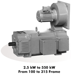
Crompton Greaves Ltd, a name synonymous with
rotating machines have DC Motors Technology
inherited from SIEMENS, Germany, the pioneer and
world leader in DC Motors. Today, Crompton Greaves
offers an entire range of world class DC Motors.
The motors are manufactured at Crompton Greaves
Ltd. Ahmednagar factory, an ISO accredited set up
having state - of - the - art manufacturing
facilities. The high quality standards maintained in
manufacturing and testing give superior electrical
and mechanical features - making the motors most
suitable for operating in tropical environments. |
| |
The Ahmednagar factory - manufacturing DC Motors
 |
| |
| |
SPECIAL FEATURES |
|
APPLICATIONS |
Fully laminated yoke construction offering
excellent commutation - suitable for 6 pulse
thyristor power supply |
|
Plastic Extruders |
|
Skewed Rotor construction - ensuring low
noise |
|
Printing Machines |
|
Vacuum pressure impregnation for armature
winding - ensuring high insulation strength |
|
Steel Rolling Mills and Wire Rod Mills |
|
High dynamic response |
|
Sugar Industry
|
Compact, low weight and highly energy
efficient |
|
Textile Mills
|
Larger size of bearings - for longer life
and
trouble free operations |
|
Apron Feeders
|
|
Constant / uniform pressure brush holders |
|
Machine Tools
|
|
Easy fitting and retro-fitting of filters |
|
Rubber Industry
|
| |
|
Cement Mills
|
| |
|
Cable Industry
|
| |
|
Paper Mills
|
| |
|
Material Handling |
| |
|
|
|
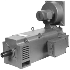
Laminated Yoke DC Motor manufactured at
Ahmednagar |
|
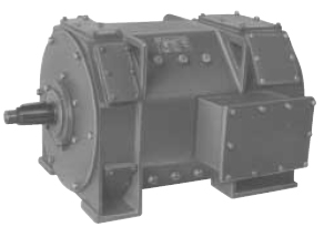
Aux Mill Duty DC Motors as per IPSS/AISE
Standards are also manufactured |
 |
|
 |
|
| |
|
|
| |
SPECIFICATIONS :Laminated Yoke
|
Laminated Yoke Construction Range : |
|
| Output Frames |
: 2.5 kW to |
550 kW
|
: ASBG 100 to ASBG
315 |
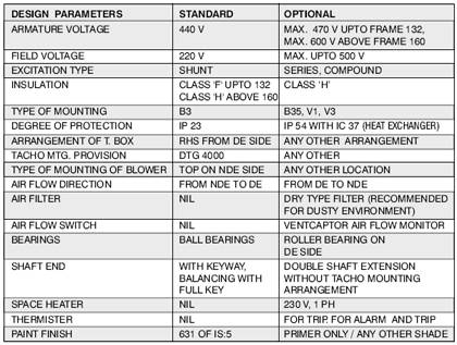 |
| |
BRUSH
LIFETIME :
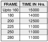 |
BRUSH MATERIAL, COMMUTATION :
Practically sparkless commutation with
converter feeding, even under overload
conditions is achieved. As a result, the
brushes have an extremely long life. |
|
|
|
|
|
| |
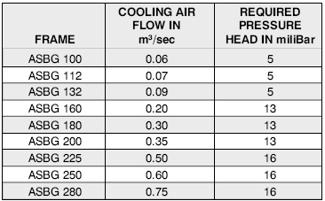
FORCED
COOLING DETAILS
 |
|
The blowers of DC Motors have three phase motors
with wide range of winding and supply voltages.
The blower motors are selected strictly in
accordance with the air quantity required and
ensures cool running of motors under the
specified operating loads / overloads. The
terminal box of blower motors are easily
assessible. |
|
| |
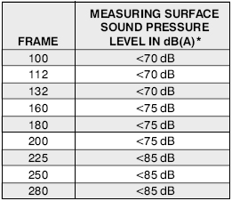
NOISE
LEVEL
 |
|
The noise levels of the motors have been
calculated in accordance with DIN EN 21 680 and
are well below the values permitted by EN 60034
- 9. They have been achieved both by means of
design measures and by optimising the magnetic
circuit and the separately driven fans.
* At No Load, with
blower ON, with thyristor supply |
|
| |
| TECHNICAL DATA |
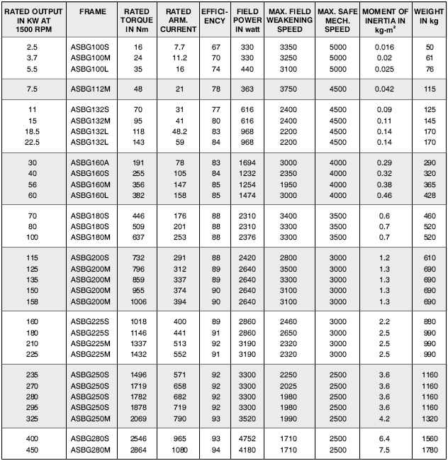 |
|
| |
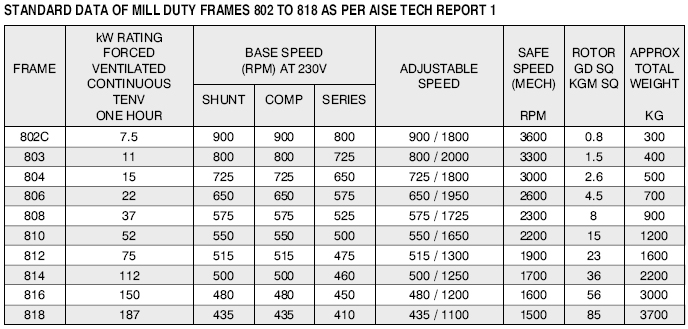
AUX MILL DUTY D.C. MOTORS TO AISE/IPSS STANDARDS
Crompton Greaves Ltd., a name
synonymous with rotating machines backed by its long
proven expertise in the field of DC motors offers the
entire range of state of art Auxiliary Mill Duty 800
series DC motors in frames 802 to 818 from 7.5 kW at 900
RPM to 187 kW at 435 RPM to AISE/IPSS Standards.
These motors are very rugged, reliable and
suitable for steel mills or like applications.
818, 816, 814, 812, 810, 808, 806, 804, 803 &
802 frames are manufactured at CGL, LT Motors Division,
Ahmednagar (Lam yoke DC motor frames 100 to 280 are also
manufactured here). M3 Division is accredited with by
BVQI for ISO 9001 Certification Quality Management
System. |
| |
|
SALIENT FEATURES |
|
|
|
• Conforming to AISE technical report no. 1-1991 /
IPSS 1-03- 002-94. |
|
• Replaceable shaft. |
|
Full speed, half speed and quarter speed designs
available. |
|
• Double
shaft extension 1:9.6 taper with key way paralle to
taper as per AISE or 1:10 taper with key way
parallel to shaft axis as per IPSS. |
|
• Suitable for operations upto 500 volts. |
|
•
Convertible between TENV & TEFV enclosure or with
top mounted blower unit. |
|
• Suitable for operation on 3 phase, 6 pulse
thyristor converter. |
|
• Loose
hanging leads or terminal box as required. |
|
• Class 'H' insulation with class 'F' temperature
rise limits. |
|
• Axial
play of 3 mm approximately of shaft. |
|
• Armature class 'H' with VPI in solventless
polyesterimide resin. |
|
• Brush
position of 45 deg. for easy access for maintenance
(except in case of laminated yoke version). |
|
• TIG welding of armature coil connection to
commutator. |
|
Motor
mounting dimension can be matched to replace 600
series motors to AISE or Russian standard. |
|
• Split / Non split yoke without compensating
winding or non split laminated yoke with
compensating winding. However split yoke is
preferred for 808 & above frames and compensating
type for 812 & above frames. |
|
|
|
| |
 |
| |
Top |
|
|
| |
AC
Generators |
| |
|
|
AC Generators |
|
| |
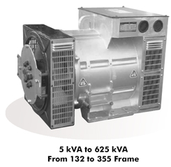
Crompton Greaves AC Generators are state-of-the-art,
self-excited, self-regulated and dependable source
of power.
A modern integrated manufacturing facility for
rotating machines, ISO 9001 certified by BVQI UK,
with structured TQM and 6 SIGMA implementation and
SAP/R3 enabled, also houses dedicated plant for AC
Generators deploying superior techniques and
processes in each specialized field of design,
material
specifications and procurement, CNC machining,
assembly, testing & packing.... with stringent
quality standards predominating throughout.
These generators incorporate advanced European
Technology and are designed for optimum performance
using high-end software solutions. With
well-qualified engineers and technocrats, backed by
a strong R & D Team, Crompton Greaves have fully
harnessed long experience in design and software to
offer a range of innovative, reliable and efficient
AC Generators. |
| |
|
|
| |
SPECIFICATIONS AND OPTIONAL FEATURES :
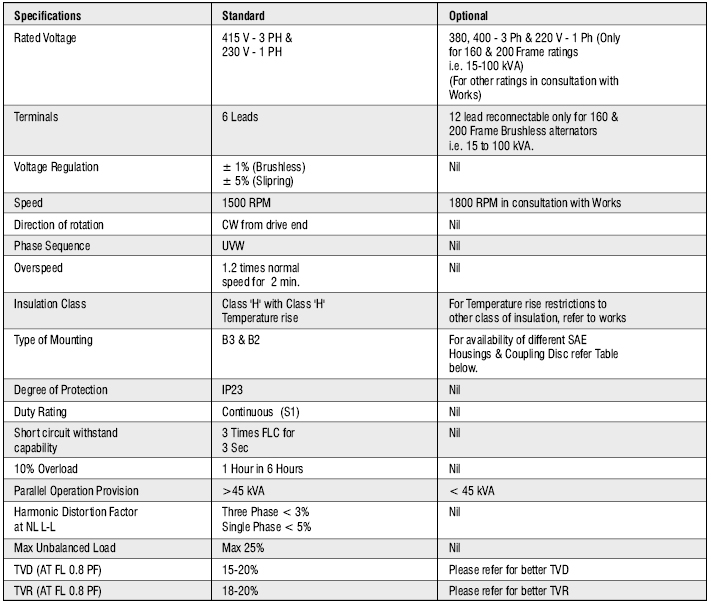
|
| |
BRUSH
LIFETIME :
 |
BRUSH MATERIAL, COMMUTATION :
Practically sparkless commutation with
converter feeding, even under overload
conditions is achieved. As a result, the
brushes have an extremely long life. |
|
|
|
|
|
| |
FORCED
COOLING DETAILS
|
SPECIAL FEATURES |
|
RANGE |
|
APPLICATIONS |
| |
| • Ease of
maintenance with integrated components and
outboard Exciter/Rotating Rectifier. |
| • A reliable
long life with superior class 'H'
insulation. |
| • Higher motor
starting capability. |
| • Compact,
light and sturdy die cast aluminum stator
for frames upto 250, offer superior finish. |
| • Specially
designed compact slipring and brush
assembly. |
| • High
thyristor load withstand capability for
Cell-Phone and Telecom applications. |
| • Short circuit
withstand capability. |
| • Wide range of
coupling discs / adaptor for single bearing
construction suitable for wide range of
Engine makers. |
| |
|
|
|
Brushless AC Generators : |
| • 5 kVA to 625
kVA, in 3 phase, 415 V, 50 Hz, 0.8 pf (lag)
Single or double bearing. |
| • 5 kVA to 40
kVA in single phase, 230 V, 50 Hz, 0.8 pf
(lag) Single & double bearing |
| |
|
Slip-Ring AC Generators : |
| • 5 kVA to 82.5
kVA, in 3 phase, 415 V, 50 Hz, 0.8 pf (lag)
Single or double bearing. |
| • 5 kVA to 20
kVA in single phase, 230 V, 50 Hz, 0.8 pf
(lag) Single & double bearing |
| • 2 Pole
Alternators (both Slipring and Brushless)
are available on request. |
| |
|
 |
|
| |
| • Industries |
| • Telecom,
Cell-Phone Towers |
| • Defense |
| • Agriculture |
| • Marine |
| • Hotels,
Hospitals, Commercial & Residential
Complexes, Petrol pumps |
| • Construction
sites, Stone Crushers & hot Mixing plants. |
• Trailer
mounted mobile sets for rental
markets |
| |
|
|
|
| |
| OPERATING
IN DIFFERENT ENVIRONMENTS |
| • For use
of the AC Generator at altitudes higher than 1000 m.
above the sea level, it is necessary to derate by a
factor of 4% for every 500 m above 1000 m |
| • If the
ambient temperature exceeds 40 deg. C, the derating
factor to be incorporated is 4% for every 5 deg. C
of increase. |
| |
|
| |
|
STANDARDS COMPLIANCE |
|
• IEC : 34 |
|
| • BS :
5000 (Part 99) |
|
|
• EN : 50081 |
|
• IS : 4722 & 13364 (Part I & II) with CE mark for
brushless designs. |
|
| |
| MECHANICAL
FEATURES |
| •
Aluminium frame die - cast stator upto 250 and steel
stator for higher frames. |
| • Sturdy
cast iron endshields fixed on to the stator frame by
high tensile screws. |
| • High
quality steel shafts are amply designed to take care
of overload and short circuit stressed conditions. |
| • Sturdy,
dynamically balanced rotors are designed for
withstanding the runaway engine speed and are with
continuous damper cage for high performance under
arduous conditions of parallel operations. |
| • Aluminum
fans for effective cooling extends the winding life. |
| • Screens
or louvered covers on all openings for safety. |
| • Easy
mount SAE adaptors are offered with single bearing
AC Generators to simplify coupling with popular
engines. |
| |
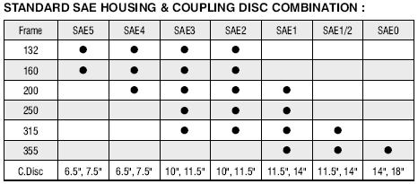 |
|
| |
|
AUTOMATIC VOLTAGE REGULATOR (AVR) |
|
Model |
Frame |
SR 7/3
SR 7/6
UVR 7
SR 7/5 |
132 & 160
Frame
200 & 250 Frame
250L & Above
For Slipring (on request) |
| • Under
Speed Protection with LED indicator. |
| • Over
Excitation Protection with LED indicator |
| • 2
Phase sensing with Senseloss LED Indicator |
| •
Designed for Thyristor load without additional
filter circuits. |
| •
Moulded construction for protection against
shocks, vibrations and adverse atmospheric
conditions. |
| •
Parallel operation facility for SR 7/6 and UVR
7. |
|
|
|
| |
| UNDER
SPEED PROTECTION (with AVR) |
| •Protects
both the AC Generator and V/f sensitive loads. The
AVR has provision for setting the frequency below
which voltage dropping occurs linear to speed. This
feature also enables the prime mover to recover the
speed faster during motor starting |
| |
| WINDING
AND INSULATION SYSTEM |
•The
armature coils of the stator main winding are made
from dual coated, class 'H' copper wires,
Single/Double Layer concentric fractional pitched
winding offers simplicity, reduced overhangs, neat
look while reducing voltage distortion and superior
capability to cope with non-linear loads. The
auxiliary winding in stator provides power to the
AVR, improving the motor starting capability of the
AC Generator.
The insulation system is class 'H'. All wound
components are impregnated in an unsaturated
polyester resin of 200 class temperature. The
impregnation provides much needed rigidity and
protection against the harsh environment, typical
for the AC Generators applications |
|
|
|
RADIO INTERFERENCE |
|
The AC Generators are having negligible Radio
Frequency Interference and meets in general the
limits permitted by VDE 0875 (N) |
|
|
|
WAVE FORMS |
|
A.C. Generators are designed to give an excellent
output wave-form. The total harmonic content of
line-to-line voltage wave-form on no load is less
than 5% as per the limits specified by IEC/IS
Standards. |
|
|
|
OVERLOADS |
|
A.C. Generators are capable of delivering an
overload of 10% for one hour after every six hours
of running. an overload of 10% for one hour after
every six hours of running. |
|
|
|
MOTOR STARTING DUTY |
|
Each kVA of AC Generator is capable of starting 1 HP
of Induction Motor with use of auxiliary winding
except for Submersible Pump & Lift Duty
applications. (Upto 200 frame slipring type only) |
|
|
|
VIBRATION AND NOISE |
CNC machining with close tolerances and repeat
Accuracy for uniform air - gap and rotor dynamic
balancing for low vibrations ensure efficient,
smooth and silent
performance. |
|
| |
TERMINATION
| •
Integral Terminal Box is provided for higher
reliability. |
| • Top
Terminal Box with side cable entry ensures
wiring flexibility. |
| •
Spacious terminal box accommodates all types,
including aluminum cables |
|
|
|
| |
TEFC Motors |
Energy Efficient Motors (EFF-1) |
Flame Proof Motors |
Crane / Hoist Duty Motors |
D.C. Motors |
AC Generators Alternators
Induction Motors |
Monoblock pumps |
Self priming pumps |
Submersible pumps |
|
|